2026 Best Recessed Power Tracks Why Is My Track Not Working?

Time:2026-10-24 Author:Mason
0%

A recessed power track can look sleek while hiding a surprisingly simple fault. If you are asking, “why is my recessed power track not working,” begin with the track’s power path, not the visible outlets. A tripped breaker, loose feed wire, failed driver, damaged connector, or overloaded circuit can interrupt the entire system. The symptoms matter. One dead module suggests a local contact problem. A completely dark track points toward supply or protection devices.

John Williamson, a former Minnesota State Electrical Inspector, emphasizes a practical safety rule: “Test before you touch, and verify before you replace.” That advice fits recessed systems especially well. Their wiring sits behind panels, cabinetry, or ceilings, where rushed inspection can create bigger problems. Turn off the circuit before removing any trim. Confirm the circuit is actually de-energized with an appropriate tester. Never assume a wall switch has isolated every conductor.

This guide examines the most common reasons a recessed power track stops working in 2026. It covers breaker checks, connector alignment, track compatibility, loose terminations, heat damage, and installation mistakes. It also explains when a qualified electrician should take over. Experience shows that users often replace the track too quickly. That can waste money. It can also conceal the original fault. A careful diagnosis is slower, but usually clearer. Even so, some failures are not obvious from the outside. That is where professional testing earns its value.
2026 Best Recessed Power Tracks Why Is My Track Not Working?

What Is a Recessed Power Track and How Does It Work?

A recessed power track is a slim electrical rail installed inside a ceiling or wall. Its conductors sit within an insulated channel. Compatible outlets, lights, or charging modules attach along the rail. Power flows through contact points inside each adapter. This creates flexible power locations without opening the wall again.

The system is not the same as a simple extension strip. A recessed track needs correct circuit protection, secure connections, and compatible modules.

If your track is not working, check the circuit breaker first. Then inspect whether the adapter is fully locked into position.

A loose contact, overloaded circuit, damaged rail, or incompatible dimmer can stop power. Never touch exposed conductors. A qualified electrician should test voltage and insulation safely.

The U.S. Department of Energy reports that LED lighting can use at least 75% less energy than incandescent lighting. However, efficient lighting still fails when the control system is mismatched.

I have seen installations look perfect but fail because one module used the wrong electrical specification.

Tips:

Switch off power before inspection. Check the product’s voltage, load rating, and adapter type. Leave space between high-load devices. Do not force a stiff connector.

The IEA’s Energy Efficiency 2023 report states that buildings consume about 30% of global final energy. Better power planning matters. Still, “best” depends on room use, circuit capacity, maintenance access, and installation quality.

How to Identify the Cause of a Nonworking Power Track

2026 Best Recessed Power Tracks: Why Is My Track Not Working?

A dead recessed power track usually has a simple cause. Check whether every connected fixture is off. If so, inspect the circuit breaker, residual-current device, or GFCI outlet. Do not reset a breaker repeatedly. NFPA reported that electrical distribution and lighting equipment contributed to an average of 32,620 U.S. home structure fires annually from 2015 to 2019. Safety must guide every test.

Turn off power before touching the track. Use an approved tester to confirm the circuit is de-energized. A qualified electrician should handle concealed wiring. If only one section fails, inspect its connector, end feed, and contact pins for looseness or discoloration. One small gap can stop the entire module. Check the track’s rated voltage and load. An incompatible dimmer may cause flickering or silence.

Look closely.

If the track works intermittently, heat marks may indicate a poor connection or excessive load. Dust can affect exposed contacts, but cleaning is not a cure for damaged parts. The U.S. Consumer Product Safety Commission repeatedly identifies loose connections and faulty wiring as serious fire hazards in electrical products. Visual inspection helps, but it can mislead. Confirm each finding with measured voltage and continuity. A proper diagnosis also checks installation records, connector alignment, and the protective device’s trip history.

Step-by-Step Checks for Power Supply and Track Connections

2026 Best Recessed Power Tracks: Why Is My Track Not Working?

Begin with the power supply, not the track heads. Turn off the circuit breaker before opening any cover. Confirm the circuit is dead with a rated voltage tester. Then check the breaker, wall switch, and any GFCI device upstream. A tripped protective device can make a perfect track appear defective. It happens more often than expected.

Restore power only for live testing when you are qualified. Measure voltage at the supply input, then at the output terminals. Compare both readings with the installation instructions. A missing output reading may indicate a failed driver, incorrect wiring, or an overloaded circuit. The U.S. Department of Energy reports that LED lighting uses at least 75% less energy than incandescent lighting, but lower wattage does not excuse incorrect load calculations. Add every connected fixture and compare the total with the power supply rating.

Next, isolate the track connection. Switch off power again. Check that each conductor is fully inserted and that terminal screws are tight. Inspect the copper contacts for dark marks, bending, or looseness. Look closely. A single displaced contact can interrupt the entire run. Verify polarity on low-voltage systems, because reversed connections may prevent operation. I once blamed a failed driver when a connector had simply backed out. That mistake was avoidable. If insulation is damaged, connections feel hot, or voltage readings remain abnormal, stop testing and contact a qualified electrician. NFPA 70 requirements can vary by installation and local adoption.

How to Test Track Modules, Adapters, and Electrical Contacts

2026 Best Recessed Power Tracks: Why Is My Track Not Working?

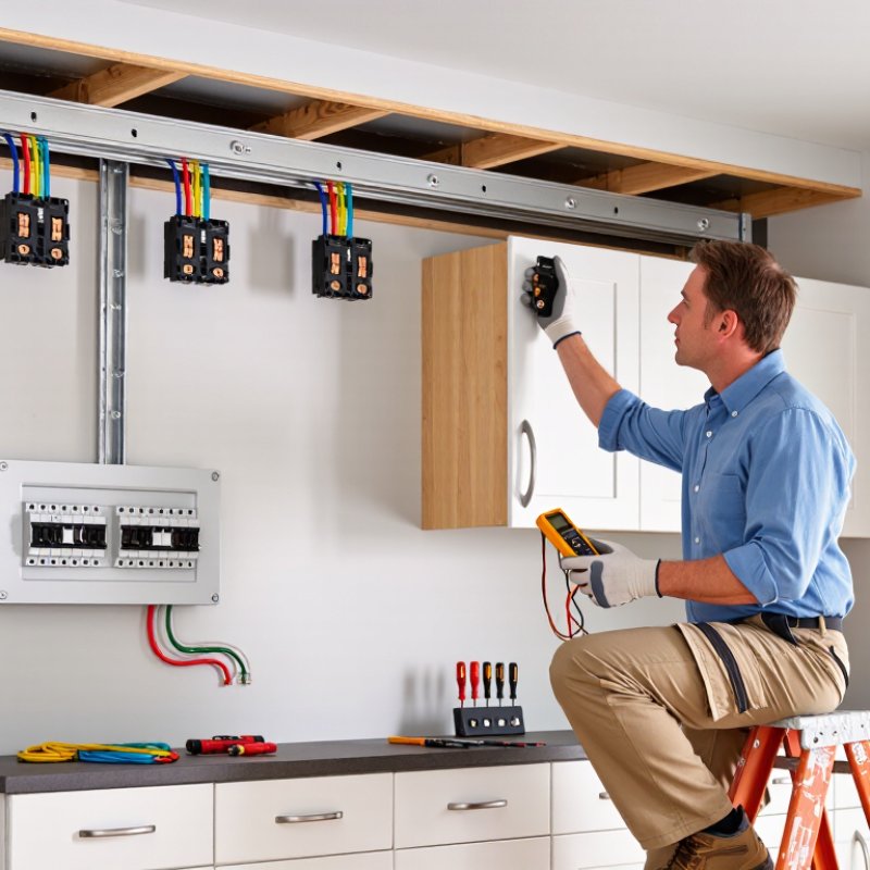
When a recessed power track stops working, do not replace every module immediately. Turn off the circuit at the breaker, then verify power is absent with a properly rated tester. Check the track’s input terminals for loose conductors, heat marks, or damaged insulation. A darkened contact may indicate overheating, not a simple connection problem.

Test each module separately. Remove it from the track and inspect its pins for bending, dirt, or uneven wear. Reinstall it firmly, then test the same module at another confirmed working position. If it fails there, the module may be defective. If it works elsewhere, the original track section or contact point deserves closer inspection. Small alignment errors matter.

Adapters need a similar check. Confirm that the adapter matches the track system and is fully locked in place. Some adapters feel secure before their contacts actually connect. Use a continuity tester only when the circuit is disconnected and isolated. Never bridge contacts or probe energized parts casually. That can damage equipment and cause serious injury.

I once blamed a faulty module, but the real issue was a slightly loose terminal. It looked harmless. That mistake changed my testing routine. I now photograph wiring positions before adjustment and retighten terminals according to the installation instructions. If voltage readings are inconsistent, stop testing and contact a qualified electrician. Hidden wiring faults are not worth guessing about.

2026 Best Recessed Power Tracks: Why Is My Track Not Working? — How to Test Track Modules, Adapters, and Electrical Contacts

Test Area Typical Symptom Power State Required Tool Test Procedure Normal Result Likely Fault Indication Recommended Action
Circuit supply and breaker The entire recessed track is dead, including all modules. Live testing only if qualified Two-pole voltage tester or multimeter rated for the circuit Check the protective device and verify voltage at the track feed terminals. Compare the measured value with the system rating and local supply voltage. Voltage is present at the feed and is within the equipment rating shown on the installation label. No voltage, a tripped breaker, a tripped residual-current device, or unstable voltage. Reset the protective device once. If it trips again, disconnect the track and have the circuit inspected by a qualified electrician.
Isolation switch and wiring junction The track works intermittently or stops after movement of the ceiling panel. De-energized Lockout device, screwdriver, continuity tester Isolate the circuit, verify it is dead, then inspect the junction box, terminal screws, push-in terminals, and strain relief. Perform a continuity check on each conductor where accessible. Conductors are secure, undamaged, and continuous with no unintended connection between line, neutral, and protective earth. Loose terminals, pinched insulation, heat discoloration, broken conductor strands, or failed continuity. Re-terminate or replace damaged wiring according to the installation instructions. Do not leave exposed copper.
Track feed connector Only one end of the track receives power, or the track operates after pressing the feed connector. De-energized for inspection Visual inspection, torque screwdriver if specified Remove power and check that the feed connector is fully seated, correctly oriented, and secured to the track conductors. Inspect the connector housing for cracks or carbon marks. The connector is locked in place and its contacts align with the track’s conductive rails. Misalignment, incomplete insertion, loose hardware, corrosion, melted plastic, or arcing marks. Replace damaged connectors. Do not scrape or bend contacts to force a fit.
Track conductive rails Some sections work while another section remains dead. De-energized Ohmmeter or continuity function Disconnect the track from the supply. Test each intended conductor from the feed point to the far end or next approved joint. Avoid relying on a buzzer alone; note the measured resistance. A continuous conductor shows a very low and stable resistance, normally close to the meter lead resistance for a short track. Open circuit, rapidly changing resistance, or a high reading compared with the conductor length. Inspect every joint and section. Replace the affected track section if the rail is cracked, interrupted, or heat-damaged.
Electrical contact pins A module works only when tilted, pushed, or moved along the track. De-energized Flashlight, magnifier, multimeter Remove the module and inspect the spring contacts or pins. Check for oxidation, contamination, loss of spring tension, and correct contact height. With power isolated, check continuity from each pin to its corresponding module terminal. Contacts are clean, resilient, aligned, and electrically continuous. Blackened metal, pitting, flattened springs, weak contact pressure, or intermittent continuity. Clean only with an approved electrical-contact method if permitted by the manufacturer. Replace worn contacts or the module.
Track module mechanical lock The module is installed but does not energize, or it can be removed without releasing the lock. De-energized for adjustment Visual inspection and installation guide Confirm that the module is inserted in the correct direction and that its locking mechanism has reached the intended position. Check that the module does not rock excessively. The module is fully seated, mechanically locked, and aligned with the conductive rails. Incorrect orientation, incomplete engagement, damaged locking tab, or excessive movement. Remove and reinstall correctly. Replace the locking component if it cannot hold the module securely.
Module input terminals One module is dead while other modules operate normally. De-energized for resistance testing; live only for qualified voltage testing Multimeter and insulated probes With the module isolated, inspect and test the connection between the contact pins and the module input terminals. If qualified, measure voltage at the module input while it is correctly installed. Continuity is stable when de-energized, and the input voltage matches the module’s marked operating voltage when energized. Open circuit, loose terminal, incorrect voltage, or voltage that collapses under load. Tighten or replace the terminal assembly as allowed. Replace a module with an incorrect or failed input stage.
Adapter or converter output The track has supply voltage, but low-voltage modules do not illuminate. Output testing by a qualified person DC voltage multimeter suitable for the adapter output Verify the adapter input first. Then measure the output without shorting the terminals and compare the polarity and voltage with the adapter label and module requirements. Output voltage and polarity match the marked specification and remain stable under the connected load. No output, reversed polarity, excessive ripple, incorrect voltage, or output that drops sharply when loaded. Disconnect the load and replace the adapter if its output remains incorrect. Never substitute an adapter with a different voltage or unsuitable current rating.
Adapter current capacity The system starts normally, then shuts down, flickers, or becomes hot. Normal operation and qualified measurement Load calculation, clamp meter where appropriate, infrared thermometer Add the rated input power of all connected modules and compare the total with the adapter’s continuous output capacity. Allow the reserve required by the installation instructions. Total connected load remains within the adapter rating, with stable operation and no abnormal heating. Overloaded adapter, repeated thermal protection, buzzing, odor, or excessive temperature. Reduce the load or install a correctly rated replacement adapter. Do not increase fuse or breaker ratings to solve an overload.
Polarity and conductor assignment Low-voltage modules remain off after an adapter replacement. De-energized before rewiring Multimeter, wiring diagram, insulated tools Confirm positive and negative conductors, or the designated system conductors, from the adapter through the feed connector and module contacts. Compare every connection with the wiring diagram. Conductors are connected to the correct terminals with no reverse polarity or short circuit. Reverse polarity, short between conductors, or a feed connector designed for a different circuit arrangement. Correct the wiring only after isolation. Replace components damaged by incorrect polarity.
Dimmer, sensor, or control module The track works from a direct feed but not through the control device. Follow the device rating and safety procedure Voltage tester, control-device instructions Confirm that the control device is compatible with the module type, voltage, load range, and control method. Check its input and output connections. The control device is correctly wired and provides the required output across its specified operating range. Incompatible load type, minimum-load issue, failed sensor, incorrect neutral connection, or control output absent. Use a compatible control device or bypass it temporarily only for qualified diagnostic testing.
Grounding and protective earth The system trips protection, gives a tingle, or shows visible damage. De-energized; specialist testing required Approved installation tester or multifunction tester Do not continue operating the system. Isolate the supply and have protective-earth continuity and insulation resistance tested by a qualified electrician. Protective earth is continuous and insulation results comply with applicable electrical regulations and equipment requirements. Missing earth, insulation breakdown, earth leakage, moisture ingress, or damaged metalwork. Keep the circuit isolated until the fault is repaired and the required safety tests pass.
Moisture, dust, and contamination Flicker, intermittent operation, corrosion, or visible residue around recessed parts. De-energized Flashlight, moisture inspection, approved cleaning materials Inspect the track cavity, connectors, and contacts for condensation, construction dust, grease, or liquid entry. Check whether the installation location matches the product’s environmental rating. Components are dry, clean, corrosion-free, and installed within their environmental limits. Water marks, green or white corrosion, dust packed into contacts, or installation in an unsuitable location. Correct the source of moisture or contamination and replace compromised electrical parts. Do not energize wet equipment.
Thermal condition Light output decreases after extended operation or the system shuts down after warming. Normal operation; inspect only when safe Infrared thermometer or thermal camera Compare temperatures at the adapter, feed connector, module, and track joints under normal load. Use the equipment instructions for acceptable limits. Temperature remains within the specified operating range with no localized hot spot. Hot connector, discolored insulation, repeated thermal shutdown, blocked ventilation, or overloaded component. Switch off the system, correct the load or connection, and replace heat-damaged parts before reuse.
Module LED driver or lamp Power reaches the module, but the light source remains off. De-energized for removal; live testing only if qualified Multimeter, compatible replacement module Verify the module input voltage first. If the correct voltage is present and contacts are sound, compare operation with a known-good compatible module. A compatible replacement operates normally under the same track conditions. Failed LED driver, open internal connection, incompatible module, or damaged light source. Replace the complete module or approved internal component; do not bypass the driver.
Final functional test The original fault appears resolved but reliability is uncertain. Normal operation after reassembly Voltage tester, visual inspection, operating controls Reassemble all covers and retainers, restore power, operate every module and control repeatedly, and observe for flicker, heat, noise, odor, or movement. All modules operate consistently, connections remain secure, and no abnormal heat, noise, or odor is present. Recurring flicker, smell, buzzing, hot spots, nuisance tripping, or loose modules. Turn off the circuit and arrange professional inspection instead of continuing repeated resets.
Safety note: Turn off and isolate the circuit before opening a track, adapter, module, connector, or ceiling access point. Verify absence of voltage with an appropriate tester. Live-voltage measurements, insulation tests, protective-earth tests, and repairs to fixed wiring should be performed by a qualified electrician in accordance with local electrical regulations.

When to Repair, Replace, or Professionally Inspect the Track

A nonworking recessed power track deserves diagnosis, not immediate replacement. Switch off the circuit breaker before touching the track. Check whether the breaker trips again, the switch feels loose, or the outlet modules remain dead. Flickering, buzzing, heat, browning, or a burning smell requires professional inspection. Do not repeatedly reset the breaker.

Repair may suit a loose cover, failed module, or damaged accessory when the track body and wiring remain sound. Replacement is safer when aluminum rails are bent, insulation is brittle, terminals are charred, or faults return after repair. NFPA’s Electrical Distribution and Lighting Equipment in Home Fires report recorded an annual average of about 25,700 home fires involving this equipment from 2016–2020. Small warning signs deserve respect.

A qualified electrician should inspect concealed connections, grounding, circuit loading, and compatibility with the installed power supplies. This matters more in older renovations, where drawings may be missing. The U.S. Department of Energy reports that LED lighting can use at least 75% less energy and last up to 25 times longer than incandescent lighting. However, a longer-lasting lamp cannot correct a loose conductor or overheated track. I have seen people replace lamps repeatedly while ignoring a warm connector. That is an easy mistake. Record the fault, photograph discoloration, and ask for a written test result before approving replacement.

2026 Best Recessed Power Tracks: Why Is My Track Not Working?

Use these reference voltage readings to decide whether the track should be repaired, replaced, or professionally inspected. Values are based on a nominal 120 V AC installation and may vary by local electrical system.

How to interpret the results: A reading near 120 V at the supply but 0 V on a track section usually indicates an open connection, damaged conductor, or failed connector. If voltage is present but the connected fixture still does not operate, inspect the contacts and fixture. Repeated tripping, heat, burning odor, visible damage, or unstable readings require professional inspection before further use.

FAQS

What is a recessed power track?

It is a slim electrical rail installed inside a ceiling or wall. Its insulated channel carries power to movable outlets, lights, or charging modules. The modules connect through internal contact points. Power locations can change without opening the wall again.

How does a recessed power track differ from an extension strip?

A recessed track needs proper circuit protection and secure connections. It also requires compatible adapters and modules. An extension strip is usually a separate plug-in device. Do not treat the track like a simple strip.

Why has my recessed power track stopped working?

Check the circuit breaker, wall switch, and upstream protective device. A tripped device may make a working track appear defective. Then inspect the adapter’s locking position. A loose contact can interrupt the whole track. Look closely.

How should I check the power supply safely?

Switch off the circuit breaker before opening any cover. Confirm the circuit is dead with a properly rated voltage tester. Only qualified people should perform live voltage tests. Check the supply input and output readings against the instructions. Do not guess.

Can too many fixtures overload the track?

Yes. Add the wattage of every connected fixture and module. Compare the total with the power supply rating. Leave space between high-load devices. Lower-wattage lighting still needs correct load calculations. Small mistakes matter.

How can I test a track module or adapter?

Turn off power and verify that it is absent. Remove the module and inspect its pins for dirt, bending, or wear. Test it at another confirmed working position. If it fails there, the module may be defective. If it works elsewhere, inspect the original contact point.

What physical signs suggest a connection problem?

Look for dark copper marks, loose terminals, bent contacts, or damaged insulation. Heat marks may indicate overheating rather than a simple loose connection. A connector can feel secure while remaining electrically disconnected. Do not force a stiff connector.

When should I contact a qualified electrician?

Stop testing if insulation is damaged or connections feel hot. Seek help when voltage readings remain abnormal or inconsistent. Hidden wiring faults are unsafe to troubleshoot by guessing. I once blamed a failed module, but a loose terminal caused the problem. That mistake was avoidable.

How can lighting efficiency affect track performance?

Efficient lighting can reduce energy use, but it cannot fix mismatched controls. Check the voltage, load rating, dimmer compatibility, and adapter type. A visually perfect installation may still fail electrically. Room use, circuit capacity, access, and installation quality all matter.

Conclusion

A recessed power track is an integrated electrical rail installed within a surface, ceiling, wall, or furniture system. It distributes power through concealed conductors and allows compatible modules, adapters, or accessories to connect at selected points. If you are asking, “why is my recessed power track not working,” begin by checking the main power source, circuit breaker, wall switch, and any connected control system. Confirm that the track is receiving power and that all wiring connections are secure, correctly positioned, and free from visible damage.

Next, inspect each module and adapter individually, looking for loose contact points, poor alignment, overheating, or signs of wear. Testing components one at a time can help identify whether the problem is caused by the track, a removable accessory, or an electrical contact. Turn off power before performing any inspection, and avoid opening concealed wiring unless you are qualified to do so. A simple connection issue may be repairable, while damaged conductors, repeated failures, or unexplained power loss may require track replacement or professional inspection.

Mason

Mason

Mason is a seasoned marketing professional with a deep expertise in the company's offerings and a passion for driving brand awareness. With a strong background in digital marketing strategies, he has an innate ability to connect with diverse audiences and effectively communicate product benefits.......